Previous
Next
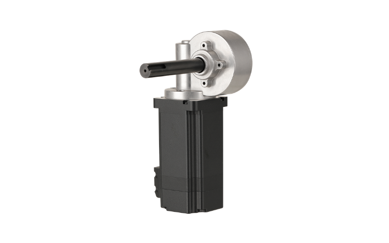
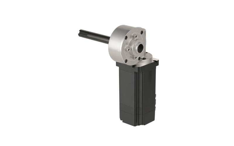
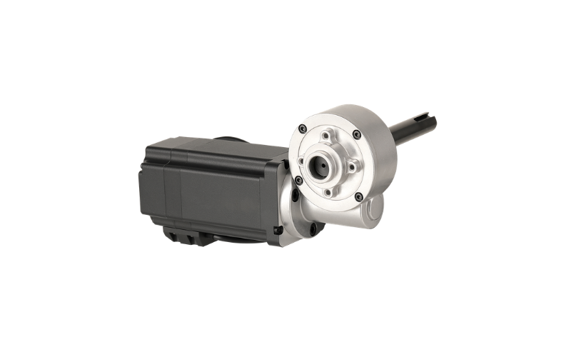
AW60BLF Series — 60mm BLDC Motor with Worm Reduction Gearbox
The AW60BLF series pairs Apexwell's 60mm-diameter, 48V brushless DC motor with an NMRV040 worm reduction gearbox, scaling rated output power from 100W to 400W across four body lengths. With reduction ratios from 7.5:1 to 100:1 and a fixed 40 N·m maximum permissible torque, this series delivers more than 2.5x the gearbox torque capacity of the AW57BLF worm-gear line from the same right-angle NMRV platform.
Shared Motor Specifications (all models)
| Parameter | Value |
|---|---|
| Winding Configuration | Star (Y) |
| Hall Sensor Position | 120° |
| Insulation Class | Class B |
| Ambient Temperature | -20°C to +50°C |
| Insulation Resistance | ≥100 MΩ (500 VDC) |
| Dielectric Strength | 700 VAC, 1 minute |
| Number of Poles | 8 |
| Number of Phases | 3 |
| Nominal Voltage | 48 VDC |
| Rated Speed | 3,000 RPM ±10% |
Motor Model Comparison
| Model | Rated Torque | Rated Current | Output Power | Peak Torque | Peak Current | Body Length | Mass |
|---|---|---|---|---|---|---|---|
| AW60BLFA78-430 | 0.32 N·m | 3.2 A | 100 W | 0.96 N·m | 9.6 A | 78 mm | 0.85 kg |
| AW60BLFA99-430 | 0.65 N·m | 5.3 A | 200 W | 1.95 N·m | 15.9 A | 99 mm | 1.25 kg |
| AW60BLFA120-430 | 0.95 N·m | 8.3 A | 300 W | 2.85 N·m | 24.9 A | 120 mm | 1.70 kg |
| AW60BLFA141-430 | 1.28 N·m | 11.5 A | 400 W | 3.84 N·m | 34.5 A | 141 mm | 2.10 kg |
Torque constant ranges from 0.094 to 0.116 N·m/A; back-EMF constant ranges from 8.01 to 8.88 Vrms/kRPM. Rotor inertia scales from 0.31 to 1.01 kg·cm² with body length.
NMRV040 Worm Reduction Gearbox Specifications
| Parameter | Value |
|---|---|
| Reduction Ratio | 7.5, 10, 15, 20, 25, 30, 40, 50, 60, 80, 100 |
| Gearbox Length (L1) | 120 mm |
| Max Torque Moment | 40 N·m |
| Transmission Efficiency | 60% |
| Weight | 2.3 kg |
Eleven reduction ratios are available (7.5 to 100:1) on a fixed gearbox footprint — the same NMRV040 gearbox used on Apexwell's AW60HS stepper worm-gear series. Max torque moment, length, and weight stay constant across the entire ratio range.
Wiring
Each AW60BLF motor exits with a 3-core sheathed power cable for the U/V/W windings and a separate 5-core shielded Hall sensor cable (+5VDC, GND, HU, HV, HW) at a 120° Hall electrical angle for standard 6-step commutation.
Typical Applications
With a right-angle output and gearbox torque up to 40 N·m, the AW60BLF worm-gear series fits heavier gate and door actuators, industrial valve and damper drives, lift and tilt mechanisms, and other applications where the AW57BLF's torque range isn't enough and the load needs to hold position without continuous motor power.
Why Choose the AW60BLF Worm Gearmotor
The right-angle output lets the gearbox change direction in the mechanical layout without an additional bevel or belt stage, and worm gearing at higher reduction ratios typically resists being back-driven by the load — useful in lifting, tilting, or holding applications where position needs to stay put if power is lost. Eleven reduction ratios on one fixed-envelope gearbox let torque and output speed be tuned without changing the mounting footprint. Custom shaft configurations and encoder feedback are available on request.
We can customize the electrical parameters of the motor and geometric dimensions such as the motor output shaft size according to customer requirements. Accessories including pulleys, eccentric gearboxes, planetary gearboxes and encoders can also be added. For more products and detailed specifications, please download the product catalog from the Download Center.